Poorly documented defect evidence is one of the leading causes of failed insurance claims, disputed dilapidation settlements, and inconclusive expert witness reports in the UK property sector. A surveyor who understands how surveyors should document building defects with photos, measurements, and sketch plans does not just record what is visible — they build a defensible evidence trail that holds up under legal and professional scrutiny. This article sets out a practical, step-by-step framework for producing that evidence, covering photographic standards, measurement protocols, sketch plan methodology, and the common gaps that undermine otherwise competent surveys.
Key Takeaways
- Every defect record must combine photographs, precise measurements, and a referenced sketch plan to be considered complete and defensible.
- Photographs should be taken at three scales: context, mid-range, and close-up, with a scale reference in every close-up shot.
- Measurements must be recorded in a consistent unit, cross-referenced to the sketch plan, and supported by calibrated equipment.
- Sketch plans do not need to be architectural drawings, but they must be legible, dimensioned, and keyed to the photographic record.
- Evidence gaps — missing reference shots, unlabelled images, or undimensioned sketches — are the most common reasons defect documentation fails in disputes.
Why Defensible Defect Evidence Matters
A building survey is only as useful as the evidence it produces. Whether the output is a RICS building survey for a prospective buyer, a schedule of dilapidations at lease end, or an expert witness report for litigation, the underlying defect record must be capable of withstanding challenge.
Courts, insurers, and opposing surveyors will test documentation on three grounds:
- Accuracy — do the measurements and photographs correspond to the actual condition at the time of inspection?
- Completeness — has the surveyor captured enough context to rule out alternative explanations?
- Traceability — can every photograph and measurement be located on a plan and linked to a written description?
When documentation fails on any of these grounds, the surveyor's professional opinion becomes vulnerable. The RICS Professional Standards and Guidance note that surveyors must provide clear, objective, and verifiable evidence to support their findings. Vague descriptions unsupported by scaled evidence are not sufficient.
"The quality of a survey report is ultimately determined by the quality of the evidence gathered on site, not the quality of the writing alone."
Understanding how surveyors should document building defects with photos, measurements, and sketch plans is therefore not an administrative task — it is a core professional competency.
The Three-Layer Documentation System
Effective defect documentation operates on three layers that work together: the photographic record, the measurement record, and the sketch plan. Each layer supports the others. Removing any one layer creates evidence gaps that are difficult to repair after the site visit.
Layer 1: The Photographic Record
Photography is the fastest and most persuasive form of defect evidence. However, unstructured photography — taking dozens of images without a system — produces archives that are difficult to interpret and easy to challenge.
The three-scale rule is the foundation of professional defect photography:
| Scale | Purpose | Typical Distance |
|---|---|---|
| Context shot | Shows the defect's location within the room or elevation | 3 to 6 metres |
| Mid-range shot | Shows the defect in relation to surrounding elements | 0.5 to 2 metres |
| Close-up shot | Shows the defect detail with a scale reference | 10 to 30 centimetres |
Every defect should have at minimum one shot at each scale. For complex defects — structural cracking, significant damp ingress, or roof deterioration — multiple close-ups from different angles are advisable.
Scale references in close-up photography are non-negotiable. A crack that appears dramatic without a scale reference may be 0.3 mm wide or 3 mm wide — a difference that determines whether it is cosmetic or structurally significant. Use a dedicated photographic scale card, a coin, or a folding ruler. Avoid using a hand or finger as a scale, as this is subjective and unprofessional.
Labelling and metadata must be applied immediately. Rename image files on site or use survey software that auto-tags images with a defect reference number, date, time, and GPS coordinates. An image named "IMG_4471.jpg" is useless in a dispute; an image named "D-14_RoofSlate_NorthElevation_2026-03-15.jpg" is self-evidencing.
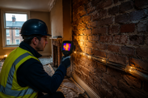
Lighting considerations significantly affect photographic quality. Raking light — a torch or flash held at a low angle to the surface — reveals crack depth, surface delamination, and settlement patterns that flat frontal lighting obscures entirely. Always carry a portable torch for this purpose, regardless of ambient light levels.
Layer 2: The Measurement Record
Photographs without measurements are opinion. Measurements without photographs are abstract. Together, they produce evidence.
What to measure for each defect:
- Crack width — use a crack width gauge (also called a crack comparator card). Record the maximum width and the width at three points along the crack's length.
- Crack length — measure the full visible extent, including any hairline continuation beyond the obvious fracture.
- Settlement or deflection — use a spirit level and steel rule to record vertical deviation. For floor deflection, a long straightedge and feeler gauges give precise readings.
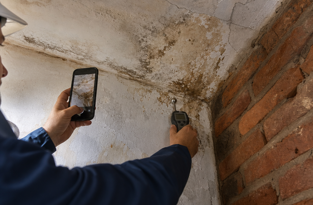
- Damp extent — record the affected area in square metres and the moisture content reading from a calibrated protimeter or equivalent meter. Note the meter type and calibration date.
- Spalling or delamination depth — use a steel rule to measure the depth of material loss.
Equipment calibration is a professional obligation. Laser distance meters, moisture meters, and crack gauges must be calibrated to manufacturer specifications and checked before each site visit. Record the equipment used and its calibration status in the survey notes. This is particularly important for dilapidation surveys where financial liability depends on precise defect quantification.
Consistent units must be used throughout a single report. Mixing millimetres and centimetres, or metres and feet, introduces transcription errors and creates confusion in cross-referencing. Adopt millimetres for crack measurements, metres for area and distance, and degrees for angular deviation.
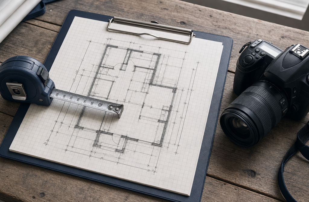
Layer 3: The Sketch Plan
The sketch plan is the spatial backbone of the defect record. It does not need to be an architectural drawing. It needs to be legible, dimensioned, and consistently referenced to the photographic and measurement records.
Minimum content for a defect sketch plan:
- Room or elevation outline with overall dimensions
- North point or orientation indicator
- Defect locations marked with a unique reference number (D-01, D-02, etc.)
- Camera positions and directions shown for each photograph
- Key dimensions confirming defect position relative to fixed points (corners, door frames, structural columns)
Grid-referenced sketching improves accuracy significantly. Divide the floor plan into a simple grid and locate defects by grid reference. This is particularly useful in large commercial buildings where verbal descriptions of location are unreliable. For commercial building surveys, a grid-referenced sketch plan is effectively a professional standard.
Digital vs. paper sketching is a practical choice. Many surveyors now use tablet-based survey apps that allow sketch plans to be drawn digitally, with defect pins dropped in real time and photographs automatically linked to those pins. This eliminates the transcription step between site notes and the final report. However, paper sketching remains reliable in environments with poor connectivity or battery constraints, provided the paper notes are scanned and archived immediately after the inspection.
How Surveyors Should Document Building Defects with Photos, Measurements, and Sketch Plans: Common Evidence Gaps
Even experienced surveyors produce incomplete defect records. The following gaps appear repeatedly in disputed survey reports and expert witness challenges.
Gap 1: Missing context shots. A close-up of a crack is meaningless if the reader cannot determine where in the building it is located. Every defect sequence must begin with a context shot that shows the defect's position within the room or elevation.
Gap 2: No scale reference in close-up images. As noted above, this is the single most common photographic failure. Without a scale reference, a crack photograph cannot be used to confirm or dispute a width measurement.
Gap 3: Unlabelled or misfiled images. Images that cannot be linked to a specific defect reference number, location, or date are inadmissible as evidence in most formal dispute processes. Implement a labelling system before the inspection begins, not after.
Gap 4: Measurements without instrument references. A moisture reading of 28% WME means different things depending on the meter used and the material being tested. Always record the instrument type, model, and the material-specific calibration setting applied.
Gap 5: Sketch plans without dimensions. A sketch that shows a crack's approximate position but does not give its distance from two fixed reference points cannot be used to re-locate the defect at a later date. This matters enormously in monitoring surveys, where the same defect must be re-measured at intervals to assess progression.
Gap 6: Failure to record inaccessible areas. When access is limited — a locked roof hatch, a sealed subfloor void, or an occupied room — this must be explicitly noted in both the sketch plan and the written record. Silence about an uninspected area implies it was inspected and found satisfactory, which is a significant professional liability.
For surveyors working on schedule of condition reporting, these gaps are especially consequential, as the schedule forms the baseline against which future dilapidation claims are assessed.
How Surveyors Should Document Building Defects with Photos, Measurements, and Sketch Plans: Technology and Software
The market for survey documentation software has matured considerably. The following tools are widely used by UK chartered surveyors in 2026:
Field survey apps such as Surveyor Assist, GoReport, and Snagg allow surveyors to capture photographs, record measurements, and annotate sketch plans on a single device. Reports can be generated automatically from field data, reducing post-inspection processing time by 40 to 60% compared to manual methods.
Laser scanning and photogrammetry are increasingly accessible for complex or high-value instructions. A 3D laser scan produces a point cloud that can be interrogated for crack widths, deflection, and settlement with millimetre precision. While the equipment cost remains significant, the evidential value for structural surveys and expert witness work is substantial.
Drone surveys provide photographic and measurement access to elevations, roofs, and areas that are unsafe or impractical to inspect from ground level. A drone survey produces georeferenced imagery that can be overlaid on a sketch plan, providing spatial context that traditional photography cannot match.
Cloud-based defect registers allow multiple surveyors working on a large site to contribute to a single, version-controlled defect record. Every entry is time-stamped and attributed to a named surveyor, creating an audit trail that satisfies both RICS standards and court disclosure requirements.
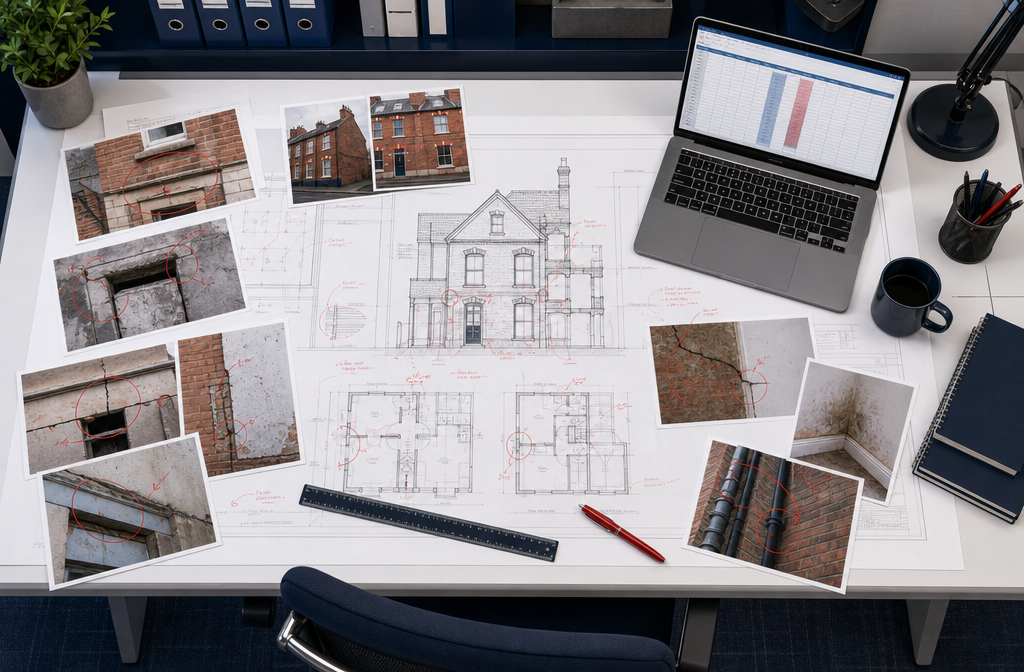
Structuring the Final Defect Report
The defect documentation gathered on site must be structured into a report that communicates findings clearly to non-specialist readers — solicitors, lenders, insurers, and property owners — while retaining the technical precision required by professional and legal standards.
Recommended report structure for defect documentation:
- Executive summary — a brief, plain-language overview of the most significant defects and their urgency classification.
- Inspection scope and limitations — explicit statement of what was and was not inspected, with reasons for any access restrictions.
- Defect schedule — a table listing each defect by reference number, location, description, severity rating, and recommended action.
- Photographic appendix — images grouped by defect reference number, each captioned with the defect reference, location, date, and a brief description of what the image shows.
- Sketch plan appendix — dimensioned plans and elevations with defect reference numbers plotted.
- Measurement data — a table of all measurements recorded, including instrument type and calibration reference.
Severity classification should follow a consistent scale. The RICS Home Survey Standard uses a three-category system (Condition Ratings 1, 2, and 3), which is appropriate for residential work. For commercial and specialist instructions, a five-point scale (from cosmetic to immediate structural risk) provides more granularity.
A RICS Level 3 building survey demands the most thorough defect documentation of any standard residential survey product, and the structured approach described above aligns directly with the output expectations of that survey type.
Conclusion
Producing defensible defect evidence is not a bureaucratic exercise — it is the professional foundation on which survey reports, valuations, and dispute resolutions are built. The framework described here — three-scale photography with scale references, calibrated and instrument-referenced measurements, and dimensioned sketch plans keyed to a consistent defect numbering system — gives surveyors the tools to document building defects in a way that withstands challenge.
Actionable next steps for surveyors:
- Audit your current site documentation process against the three-layer system described above and identify which layer is weakest.
- Introduce a standardised defect reference numbering system across all instructions, ensuring photographs, measurements, and sketch plan annotations share the same reference codes.
- Review your photographic workflow: confirm that every close-up image in your last three reports included a physical scale reference.
- Evaluate field survey software if you are still working entirely on paper — the time saving and audit trail benefits are significant.
- For any instruction that may result in a dispute, consider whether a drone survey or laser scan would provide evidential quality that conventional methods cannot match.
Surveyors who invest in rigorous documentation practices protect their clients, protect their professional reputation, and produce reports that stand up when it matters most. Whether the instruction is a RICS homebuyer survey or a complex commercial dilapidations assessment, the principles are the same: photograph it, measure it, draw it, and reference everything to everything else.
References
- Royal Institution of Chartered Surveyors. (2019). RICS Home Survey Standard. RICS.
- Royal Institution of Chartered Surveyors. (2020). Surveying Safely: Health and Safety Guidance for Surveyors. RICS.
- Royal Institution of Chartered Surveyors. (2021). Dilapidations: England and Wales, 7th Edition. RICS Guidance Note.
- Hollis, M., & Gibson, C. (2005). Surveying Buildings (5th ed.). RICS Books.
- Melville, I. A., & Gordon, I. A. (2004). The Repair and Maintenance of Houses. Estates Gazette.
- Building Research Establishment. (2018). Recognising Wood Rot and Insect Damage in Buildings (BRE Good Building Guide). BRE Press.